


ORTHOLUTION
Next Generation of Orthodontic mini-implant
-
Fracture of the orthodontic implant
- Loosening of the orthodontic implant
- Fracture of the orthodontic implant
- Treatment of the fractured tip
- Injury of periodontal tissue
- Infection and abscess
- Damage of neighboring soft tissue
- Orthodontic implant covered with soft tissue
- Pain during implantation
- Pain during mastication
- Implantation in inappropriate area
Fracture of the orthodontic implant
Fracture of the orthodontic implant
There is an intrinsic limiting factor regarding implant fracture. The torsional strength of an implant depends on the physical properties of the material and is proportional to the diameter of the cube. The best way to prevent fracture is to increase the diameter and to use stronger materials such as Co-Cr alloy; however, both of these changes are impractical. The Cr-Co alloy demonstrated lower biocompatibility than the titanium alloy, and long-term stability is not guaranteed.
The causes of orthodontic implant fracture vary according to the fracture site (figure 3); by removing the causes, the problem can be solved. In most cases, fracture does not occur at orthodontic loading or at removal.
The fracture site depends on the cause of fracture. The fracturing of implants can be prevented by elimination of the possible causes of fracture (figure 3, 4). The design of the apical tip was altered to increase the mechanical strength of the tip and a lateral cutting groove was added to prevent stress concentration (figure 5). Regarding diameter factor, since the torsional strength is proportional to the cube of the core diameter, a very small enhancement of core diameter can greatly increase the strength of a screw. The mini type should not be used where cortical bone is comparatively thick. To prevent fractures, pre-drilling through cortical bone is obligatory, particularly in areas where accessibility is poor and cortical bone is very hard, such as the mandibular posterior buccal alveolar area, buccal shelf area, and midpalatal suture area. A short implant is recommended for these areas for prevention of fracture. Modifications of the design, proper manipulation and pre-drilling procedure can minimize implant fracture.
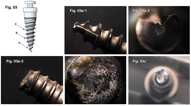
Fig. 3
Causes according to fracture area. Fractures of the "A" area or "B" area may result from lateral force produced by improper manipulations. Fracture of the "C" area may result from the intrinsic limiting factor.
- The "A" area can be broken if the insertion angle is altered while the tip of the orthodontic implant is located in the cortical bone layer.
- The "B" area can be broken if the insertion angle is changed during implantation at an area where there is hard bone, such as the lower posterior area. And it can be broken by the leverage effect with a contra-angled long driver.
- The "C" area can be broken if torque beyond the torsional strength of the implant material itself is applied during insertion. This is the mini-type, which was broken in posterior mandibular area where bone is very hard.
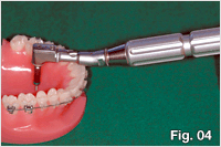
Fig. 4 Particularly in using a long driver, Class I leverage is easy to occur. So, even a small lateral force can cause fractures at an area where there is hard bone.
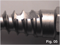
Fig. 5 During insertion, the stress is likely to be generated where the diameter start to increase, so the lateral cutting groove is incorporated to prevent stress concentrations.
- 상호 : (주)오솔루션
- 대표자 : 김정문
- 주소 : 서울 강동구 양재대로 1371 (성내동) 207호
- TEL : 02-483-1212
- FAX : 02-478-0735
- 사업자 등록번호 : 212-81-63456
- EMAIL : orlus@ortholution.com
- Copyright(c) (주)오솔루션. All Rights Reserved.

