


ORTHOLUTION
Next Generation of Orthodontic mini-implant
-
Clinical Applications
Clinical Applications
Timing of orthodontic loading
When the bone quality is adequate and stress can be distributed appropriately, immediate loading is possible.
Orthodontic applications
The mini-implant can be used in direct or indirect applications to apply continuous or intermittent force.
Clinically, one implant can tolerate 200-300gm of orthodontic force. The orthodontic mini-implant is generally used for retractive mechanics, but can also be used for pulling mechanics.
Direct application
It is possible to directly hook an elastic chain or a NiTi coil spring to the button in the upper part of the implant (figure 35, 36).
A NiTi coil spring for mini-implants or a general NiTi coil spring with metal ligature can be used. The mini-implant can be also used with removable appliances (figure 37).
But, it should be kept in mind that the bone-implant interface is weak to impact stress, so orthodontic force should first be applied to teeth or hooks and then the force can later be applied to an implant to avoid unnecessary stress to the implant.
Indirect application
Using the upper head part of an implant, splinting with teeth or an implant is possible, and various attachments can be bonded without surface treatment (figure 38).
In general, surface treatment of mini-implant heads is not necessary for bonding of attachments. Though, a sandblasting surface treatment does increase bonding strength and is recommended where bonding failure is critical.
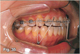
Fig. 35 The use of intra-arch fixed appliances and inter-arch elastic applications are very practical.
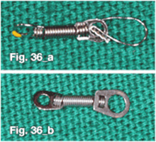
Fig. 36 The size of the mini-implant head is designed for elastic chains. So, for the use a NiTi coil spring, the metal ligature is necessary (a). But a NiTi coil spring designed for mini-implants with bigger hole can be used without any problem (b).
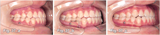
Fig. 37 Anterior crossbite was corrected by growth modification, but slight relapse occurred by late mandibular growth (a). For active retention, implants were placed between the lower 2nd bicuspid and 1st molar, and clear aligner with hook was used at night (b). Elastics were also used from implants. After 1 year follow up, occlusion was maintained (c).
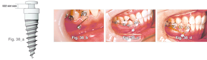
Fig. 38 There is a .022 size structure under the button (a); this space can be used for placement of the orthodontic wire (b). The wire can be attached to the implant and tooth with flowable resins (c), thus giving the individual tooth three-dimensional anchorage (d).
- 상호 : (주)오솔루션
- 대표자 : 김정문
- 주소 : 서울 강동구 양재대로 1371 (성내동) 207호
- TEL : 02-483-1212
- FAX : 02-478-0735
- 사업자 등록번호 : 212-81-63456
- EMAIL : orlus@ortholution.com
- Copyright(c) (주)오솔루션. All Rights Reserved.

