


ORTHOLUTION
Next Generation of Orthodontic mini-implant
-
Surgical procedure (Direct Approach)
Surgical procedure (Direct Approach)
Specifications & Selection of the implant If accessibility is adequate, a direct approach with a hand driver is recommended.
Required instruments
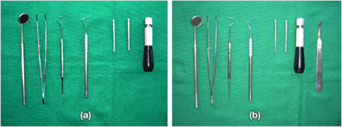
Fig. 12 Required instruments for the direct approach (a). A periodontal probe is essential for marking the insertion point on soft tissue and for bone probing. If a frenectomy is necessary, a blade holder and No. 12 blade should also be used (b).
Proper grip
The driver handle should be gripped properly according to the stage of surgical procedure and the purpose of the procedure (figure 13, 14 and 15).
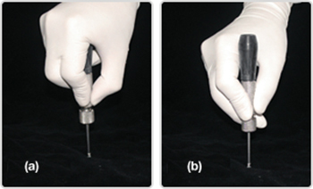
Fig. 13 The palm grip (a) is recommended for the perforating stage and the guiding stage because of its superior stability in handling. The pen grip (b) is not recommended because it allows for unwanted lateral movement.
Fig. 14 Palm grip: grasp slightly while covering the head with a palm. The driver handle is located on the palm below the index finger.
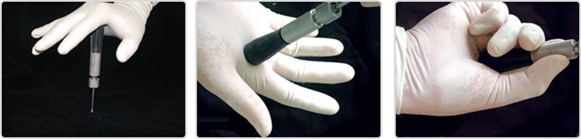
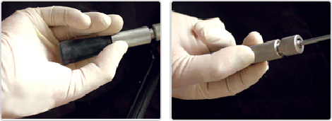
Fig. 15 For the finishing stage, it is favorable to use the finger grip because rotation should be applied very cautiously. The handle should be grasped gently with only three fingers.
Posture
In order to ensure proper surgical placement, an adequate visual field and proper accessibility are very important (figure 16, 17, 18 and 19).
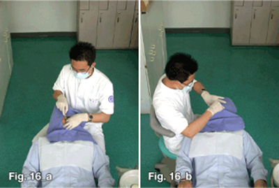
Fig. 16 In general, the ideal operator position would be from the 9 o'clock position (a) to the 1 o'clock position (b). For access to the left side, the 3 o'clock position may be better for right-handed operators. Operators should change working positions as approach for perpendicular insertion progresses to approach for oblique insertion. Throughout the procedure, no tension or stress should be placed on the wrist, the shoulder, or the neck. For example, for right-handed operators, the 12 oclock position is preferable during perpendicular insertion at the right premolar area. In oblique insertion at the right premolar area, the 9-10 o'clock position is better.
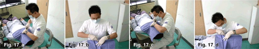
Fig. 17 The posture of an operator should be natural and unstrained for better accessibility and results (a and b). Unless the unit chair is lowered to an appropriate height, the posture of the operator may be unnatural (c and d); unnatural posture is accompanied by a decrease in accessibility.
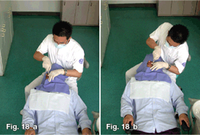
Fig. 18 For right-handed operators, a patient should turn his head completely for access to the left side (a). If the head of the patient is not in the appropriate position, the visual field may be inadequate and the posture of the operator may be unnatural (b).
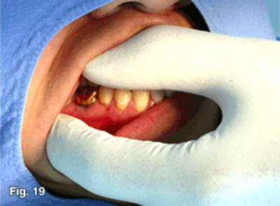
Fig. 19 It is very important that the visual field and accessibility be secured by means of sufficient retraction of the soft tissue using the hand that does not handle the driver.
Surgical procedure
The ORLUS mini-implant is designed to be placed without pre-drilling, but pre-drilling using the ORLUS Surgical drill (OS DRL-H116) is recommended to minimize surgical trauma and to prevent root injuries. By pre-drilling through the cortical bone with the ORLUS Surgical drill, surgical trauma can be reduced and iatrogenic root injury can be prevented by increased tactile sense during the surgical procedure.
1. Pre-op exam stage: site selection, anesthesia, and pre-op exam.
The implant placement site is confirmed by clinical exam and radiological exam. The anatomy of the insertion site should be checked; soft tissue conditions, such as the thickness of the attached gingiva, and frenum attachment should also be checked. There may be abnormalities of root shape, pneumonization of a maxillary sinus, abnormal localization of the accessory canal, or other issues. The location of the insertion should also be palpated to confirm the topography of the bony tissue and to determine the initial insertion angle(figure 20)
With full retraction of the soft tissue, infiltration anesthesia is administered on the mucosa (figure 21). After anesthesia, bone probing is performed to evaluate bone quality using a periodontal probe. If bone appears to be soft and is easily penetrated with a probe, the site of insertion should be changed.
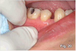
Fig. 20 Due to individual variation of the buccal slope, it is important to palpate the buccal slope to determine the insertion angle.

Fig. 21 With full retraction of the soft tissue, infiltration anesthesia is administered on the mucosa, not on the attached gingiva to reduce pain from injection.
2. Preparation & marking After the placement area is scrubbed with Betadine, the insertion site should be marked with the periodontal probe. Using a periodontal probe, the vertical reference line which bisects the interdental area parallel to the axes of the proximal teeth should be marked (figure 22). The horizontal reference line should then be marked according to the position of the alveolar crest and the required amount of vertical force. At this moment, thickness of soft tissue is also measured by the periodontal probe.
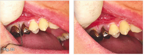
Fig. 22 After the infiltration anesthesia, the longitudinal indentation can be made on the soft tissue by the periodontal probe between the two teeth and parallel to the long axis. This line can be used as the vertical reference.
A separate incision is usually not required. However, when the implant is to be inserted in the area of a frenum, a frenectomy should accompany the procedure to prevent possible mechanical irritation around the implant during function (figure 23, 24 and 25). Frenectomies can be performed before or after implantation. The procedure is often recommened before implantation because it holds an advantage in that extra soft tissue does not remain, although it carries a disadvantage in that it requires bleeding control before implant placement. In the case of implantation on unattached gingiva, sufficient retraction of soft tissue is generally adequate. If soft tissue gets entangled during insertion, it should be loosened through counter-turning of the driver, after which the procedure can proceed. According to preference of the operator, 3mm of stab incision may be performed on the mucosa.
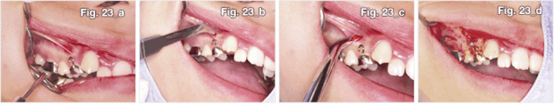
Fig. 23
Procedure of frenectomy for implant placement.
After infiltration anesthesia (a), make a horizontal incision of about 3 mm up to the periosteum using a No. 12 blade (b, c). Bleeding should be controlled by the application of pressure using wet gauze for 5 minutes. The implant should then be placed in the same way as in a normal case (d). After implantation, the patient should hold the wet gauze for approximately 15-30 minutes in order to control bleeding. Additional suturing is not necessary.
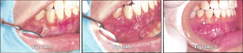
Fig. 24 A frenum was present at the site where implant placement was planned (a). Therefore, a frenectomy was performed prior to implantation (b). A stable soft tissue interface was seen one week after implantation (c).
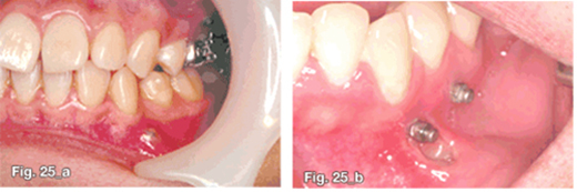
Fig. 25 If the frenectomy is omitted, ulceration of the soft tissue (a) or inflammation (b) or appears as the movement of the frenum continually irritates surrounding tissue.
3. Perforating stage: perforating through cortical bone. The perforating stage is important because cortical bone is the most resistant component to insertion and is the most important part in obtaining primary stability. Therefore, the main goals of this stage are to allow implantation to proceed easily and to protect cortical bone against unnecessary surgical trauma by cortical bone punching. There are two ways to perforate through cortical bone: using the ORLUS Surgical drill and using an implant (figure 27, 28). The former is advisable because a drill is superior to a screw in cutting efficiency, and pre-drilling can increase tactile sense during the procedure, so root-touching can be recognized. In the perforating stage, insertion perpendicular to the surface is recommended to prevent slippage on the surface. The slope of osseous tissue should be determined at an earlier stage by palpation. To perforate into cortical bone, an adequate amount of vertical force should be applied and a palm rest should be used to firmly establish the path and to turn the screw. Operations should be performed by virtue of the function of the screw, rather than by vertical force. The cortical bone should be perforated using a turning motion. In order to reduce the risk of root injury and to minimize surgical trauma, it is desirable for a manual drill system be used.
- With pre-drilling(figure 28)
The ORLUS Surgical drill is designed to perforate cortical bone. To avoid slippage, the operator should work perpendicular to cortical bone in order to perforate through cortical bone. The moment of perforation can be felt when resistance drastically decreases. After perforation, the insertion site should be drilled again with the planned angle of implantation.
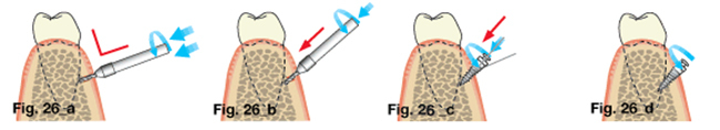
Fig. 26 Surgical procedure for the placement of mini-implants with pre-drilling
- Perforating stage I; operator should approach perpendicular to the cortical bone to avoid slippage during cortical bone perforation.
- Perforating stage II (recapitulation); insertion site should be drilled deeper followed by the planned angle.
- Guiding stage; implant is inserted according to the planned insertion angle up to about 2/3 of the full length.
- Finishing stage; only rotation should be applied without any vertical force to maximize cortical bone support.
- Without pre-drilling (figure 27) The new type of mini-implant has a screw that penetrates cortical bone without pre-drilling. In order to avoid slippage, the operator should make an approach perpendicular to the surface of cortical bone from the beginning to a depth of 1-1.5mm in cortical bone. At this time, lateral force should be avoided to prevent fracture (figure 26).After the implant is inserted to a depth of approximately 1.0mm into the cortical bone, the driver should be turned counter-clockwise in order for the screw to be drawn back fully. Due to the risk of implant fracture, a mini type implant is not recommended for placement without pre-drilling, particularly in the mandible. Operators should be very careful not to break the tip of the implant, which usually results from a change in the angle of insertion while the tip of the implant is in the cortical bone.
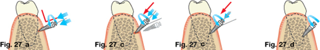
Fig. 27 Surgical procedure for the placement of mini-implants without pre-drilling
- Perforating stage I; Operator should approach perpendicular to the cortical bone to avoid slippage when perforating cortical bone to a depth of 1 to 1.5 mm
- Guiding stage I; Implant is drawn back fully to change the insertion angle.
- Guiding stage II; Implant is inserted according to the planned insertion angle.
- Finishing stage; Finishing rotation should be applied without any vertical force to maximize cortical bone support.
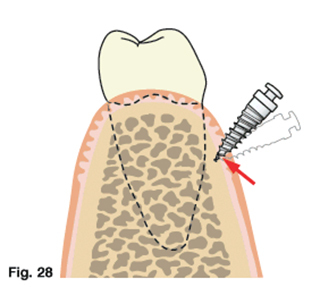
Fig. 28 The operator should be careful not to break the tip when changing the inserting angle. The tip can be broken if the inserting angle is changed while the tip is in the osseous tissue. Hence, in the case of insertion without pre-drilling, the implant should be removed completely and the procedure should then be attempted again to change the insertional angle.
4. Guiding stage: let the screw hold osseous tissue according to the planned implantation angle.
During this stage, the screw should be engaged with the bone and inserted at a planned angle. After perforation of cortical bone, an implant should be inserted up to about 2/3 of the full length according to the planned angle of insertion according to insertion site. During this stage, minimal vertical force should be applied as long as the insertion angle is maintained, and a palm rest should be used once again in order to provide a firm basis for securing the path. As in the perforating stage, the implant should be inserted by virtue of the screw function, not by vertical force. That is, it should be inserted by the turning of the driver handle. A pin or a nail is inserted by vertical force of "pushing", while a screw is inserted by means of "rotation." Slight wobbling may be allowed.
- With pre-drilling
From the beginning, an implant can be inserted according to the planned insertion angle.
- Without pre-drilling
An implant should be fully withdrawn and then inserted according to the planned angle of insertion. The insertion angle should never be changed as long as the tip is in cortical bone. Otherwise, the risk of tip fracture is high.
5. Finishing stage: : finishing and obtaining mechanical stabilization from cortical bone.
Primary stability is obtained from cortical bone during this stage, meaning that this stage is the most important in terms of early stability. The implant should be inserted to the planned depth, and the implant head should be exposed to an adequate extent according to the host bed condition.
After inserting approximately 2/3 of the full length of the screw and securing its bone engagement, implant placement should be finished with only rotational motion by a finger grip in order to maximize support from cortical bone. Because the screw engages with bone, rotational motion is enough to finish the procedure since the screw will transform this rotation into the required translation. Finishing solely by "rotation" is needed in order to maximize contact with the cortical bone and to prevent wobbling. Even a small vertical force may cause "wobbling", which causes critical damage to cortical bone and compromises primary stability.
6. Prognosis A tight fit should be felt during the final 2-3 turns of the insertion. If not, the implant is likely to fail due to a lack of cortical bone support, excessive trauma or wobbling during insertion.
- 상호 : (주)오솔루션
- 대표자 : 김정문
- 주소 : 서울 강동구 양재대로 1371 (성내동) 207호
- TEL : 02-483-1212
- FAX : 02-478-0735
- 사업자 등록번호 : 212-81-63456
- EMAIL : orlus@ortholution.com
- Copyright(c) (주)오솔루션. All Rights Reserved.

