


ORTHOLUTION
Next Generation of Orthodontic mini-implant
-
Precautions according to insertion site: Maxilla
Precautions according to insertion site: Maxilla
Maxillary buccal alveolus
For implantation in the maxillary buccal alveolus, precautions must be taken to prevent injury not only to the teeth, but also to the maxillary sinus (figure 2, 3).
The greatest advantage of using buccal alveolus area is the superior accessibility for implantation and utilization. There are two major problems with the use of buccal alveolar implants: the risk of root injury and the limitation of tooth movement. Irreversible root injury is very rare, but it is critical. However, proper treatment protocols, such as pre-drilling through cortical bone by a manual drill, accurate positioning, and oblique insertion can actually reduce or eliminate the risk of root injury.
The second problem is that implants placed in an interdental area may impede mesio-distal movement of the adjacent teeth. But, with proper treatment protocols, including off-center and oblique insertion at the area between the 2nd premolar and the 1st molar, 3mm of mesiodistal tooth movement is feasible. If more than 3mm of movement is needed, re-insertion of another implant may be useful after the teeth have moved 3mm mesiodistally.
When the implant is to be inserted in the areas of the frenum, a frenectomy should be performed to prevent possible mechanical irritation around the implant during function. And indirect approach using contra-angled instruments may be needed in the area between the 1st and 2nd molars.
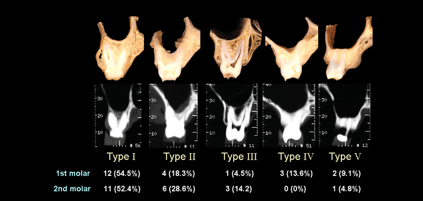
Fig. 2 Classifications of vertical relationship between the inferior wall of maxillary sinus and the roots of the maxillary molars (B: buccal, P: palatal). In any type, there is little chance to injure maxillary sinus if the apical end of an implant is located below the level of the root apex. Even in the case of sinus invasion, as long as the maxillary sinus is not severely inflamed, there are no unfavorable sequelae if the implant is removed.
Fig. 3 The distance between the maxillary teeth at 4mm (a) and 8mm (b) apical to the CEJ. The buccal space is wider than the interdental space, especially in molar areas. Precisely speaking, the space of the buccal alveolus is used for the orthodontic mini-implant instead of the interdental space. In fact, both the distance between the roots and the buccolingual space are correlated with the risk of root injury and the amount of possible tooth movement. The buccolingual space is particularly important in securing available space. That is, there is less available space where the buccolingual dimension is narrow, such as at the anterior alveolus area, premolar area, and areas where expansion has been accomplished previously with expansion appliances. More caution should be given to place implants in these areas and the fact that the mesio-distal movement of adjacent tooth is more likely to be limited should be kept in mind.
Implant selection Generally, the regular type or wide type of the implant is chosen. When an acceptable level of primary stability is difficult to obtain, the wide type implant should be used.
Determination of insertion site and insertion angle
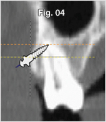
Fig. 4 When the implant is inserted obliquely, the apex of the implant is located more apically and buccally. As a result, more space can be used with oblique insertion than with perpendicular insertion. Oblique insertion causes the implant apex to be more apically and buccally located, so as to secure more space.
Determination of the insertion site (Antero-posterior positioning)
Figure. 5 For molar distalization, determine the insertion position 1-2mm distal to the imaginary central line between the two teeth(A point). For molar protraction, determine the insertion position 1-2mm mesial to the imaginary central line(C point). If there is to be no mesio-distal movement of the adjacent teeth, determine the insertion position on the central line(B point).
Figure. 6 The implant should generally be placed slightly towards the root apex rather than the mucogingival junction. For intrusion, the position of insertion needs to be determined sufficiently apically(B point), otherwise the implants will restrict further intrusion as the teeth intrude. The closer the implant is positioned to the root apex, the greater intrusive forces can be obtained and the more space can be utilized for mesio-distal movement. When the attached gingiva is narrow or the sulcus is shallow, insertion towards the root apex is restricted.
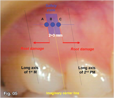
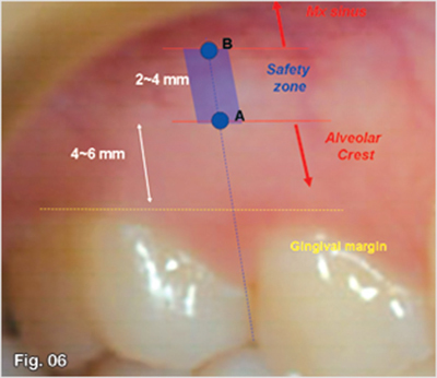
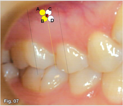
Fig. 7
Determine the insertion position according to the antero-posterior and vertical tooth movement required.
A: For intrusion & distalization
B: For distalization
C: For intrusion & protraction
D: For protraction
E: For anterior retraction
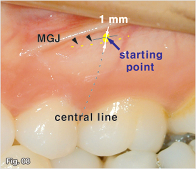
Fig. 8 Generally, a mini-implant should be inserted near the mucogingival junction. For this reason, at the start, the tip of the implant should be placed about 1 mm apically from the mucogingival junction with consideration to the diameter of the implant.
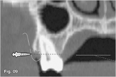
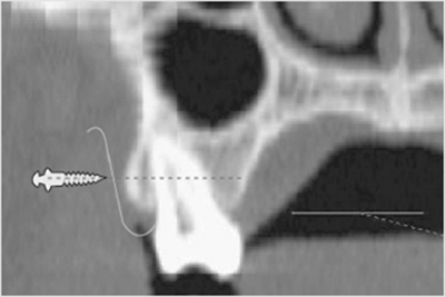
Fig. 9 The alveolar crest is located apical to the gingival margins. We should determine the vertical position of insertion while taking into consideration the location of the alveolar crest. Implants should be inserted apically enough as not to injure the alveolar crest.
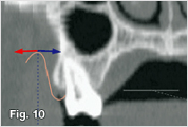
Fig. 10 An implant head or an extension wire should not be located lateral to the mucobuccal fold because of excessive stress from facial muscles, such as the cheeks. The implant should be positioned medial to the mucobuccal fold.
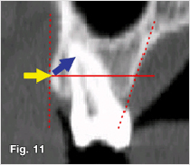
Fig. 11 Insertion at an oblique angle allows for the use of more space, reduces the possibility of root injury, and increases the surface in contact with the cortical bone. But it is preferable that the implant be inserted perpendicularly when perforating cortical bone. Therefore, the working angle for insertion changes during the procedure. But, insertion at an oblique angle may not be possible in some cases.
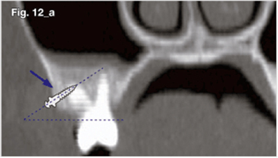
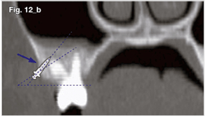
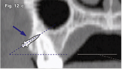
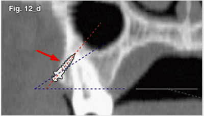
Fig. 12A sufficient quantity of cortical bone should sustain the implants even in oblique implantation. It does not matter if an implant is inserted more obliquely, as with the case seen in figure 13a (a, b). However, the quantity of bone that holds an implant may not be adequate due to the surface topography, as shown in case figure 13c (c, d). Therefore, oblique implantation may be problematic in a case such as figure 13c. The angle of insertion should be determined according to the surface topography.
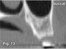
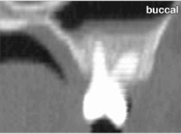
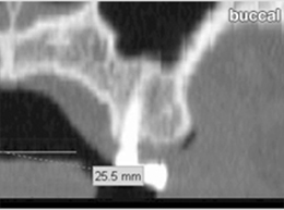
Fig. 13 The surface topography of cortical bone is diverse in different patients. Hence, it is not good to uniformly determine the insertion angle based upon the occlusal plane. The surface topography should be examined by palpation prior to a procedure. At first, it is efficient to drill or implant perpendicularly to the cortical bone because it prevents slippage on the surface. After perforating cortical bone, the angle of insertion can be changed. An angle of approximately thirty to forty-five degrees to the occlusal plane is recommended to minimize the risk of root injury and to maximize the available space.
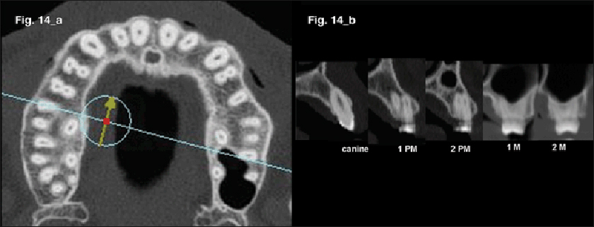
Fig. 14 Differences in the surface topography of cortical bone in the same individual depend upon the areas. In the buccolingual cross section (a), the inclination of the labial and buccal alveolar surface increases when migrating from the posterior to anterior teeth area (b).
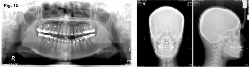
Fig. 15 When considering the surface topography of cortical bone, the angle of insertion should differ between anterior and posterior implants. In other words, the implant between the canine and the first premolar was inserted almost parallel to the occlusal plane with regards to the slope of the cortical bone surface. The implant between the 2nd premolar and the first molar was inserted obliquely at 45 degrees to the occlusal plane. It should be kept in mind that there is less available space when an implant is inserted parallel to the occlusal plane because of the location of the apical end of the implant.
Palatal Alveolus area
Caution must be taken to prevent injury to the greater palatine neurovascular bundle and maxillary sinus (figure 3, 16).
For the intrusion of the maxillary molar segment and the arch constriction, posterior palatal implants are necessary for biomechanical efficiency. Additionally, by using abundant palatal space, various attachments can be utilized to change the line of force. Cortical bone is thicker here than in the buccal area, and the keratinized gingiva is thicker. As a result, the incidence of soft tissue problems is very low. There is also more mesio-distal space available than there is buccal space. Furthermore, because transpalatal attachment is not necessary for treatment, there is greater ease of treatment as an application point of palatal force and less patient discomfort than in the midpalatal area.
There is also less accessibility to the palatal area than the buccal area. Hence, the posterior palatal area is not suitable for direct implantation. Because accessibility is lower, more skill may be required comparatively.
Patients should be instructed not to place their tongue over the implant after insertion because this could lead to loosening of the implant as a result of continuous irritation from the tongue.
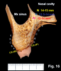
Fig. 16 The neurovascular bundle goes through the greater palatine foramen and near the palatal vault. Because it is located 12mm above the palatal cemento-enamel junction, the risk of causing injury to the neurovascular bundle is usually quite low unless the implant is inserted superior to the root apex. Moreover, we can prevent possible damage to the neurovascular bundle beforehand by examining the area with a periodontal probe at the preoperative examination.
Implant selection and determination of location and angle
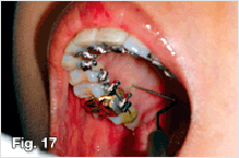
Fig. 17 Implant selection: Gingiva of the posterior palatal alveolar area has a submucosal layer containing glandular tissue, so it is relatively thick and may vary widely in individuals. Therefore, following anesthesia, the thickness of the soft tissue should be measured using a periodontal probe prior to implantation using a periodontal probe. The implant should be chosen according to the thickness of the soft tissue. If the gingival thickness of the planned position is too thick, the insertion position should be changed. If thicker than 4mm, implantation in another area should be considered. The reason for this site change should be explained to the patient beforehand. The risk of damage to the post palatine vessel can also be minimized by using this procedure.
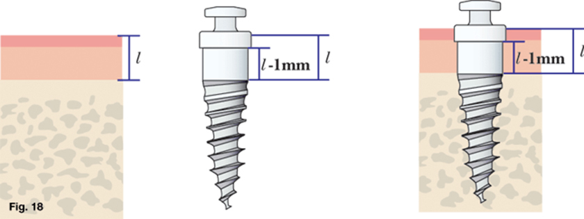
Fig. 18 Implant selection: In the maxillary palatal alveolus, an implant can be deeply inserted, because the palatal gingiva is thick keratinized epithelium. Therefore, the length of the soft tissue contact area is selected to be slightly shorter than the thickness of the soft tissue.
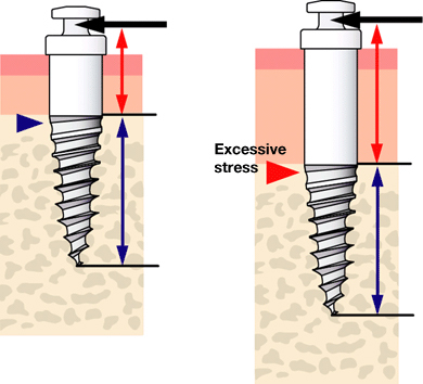
Fig. 19 Implant selection The soft tissue contact area of an implant should be 0.5 to 1.0mm shorter than measured soft tissue thickness at the insertion site considering the insertion depth. In most cases, regular type implants of a 2mm long cylindrical neck are used because the thickness of the gingiva is usually about 2-3mm. For cases with poor bone quality or thick soft tissue, a wide type implant is recommended. A depth of 6mm into the bone seems to be sufficient.
Determination of the implant site and insertion angle
Antero-posterior positioning:Insertion with a direct view is impossible, so delicate positioning for procedures such as buccal insertion is difficult. The shape of a palatal root is also checked before positioning using panoramic radiography. For posterior intrusion, insertion between the 1st and 2nd molars is recommended. For lingual orthodontic treatment, insertion between the 2nd premolar and 1st molar or between the molars is recommended.
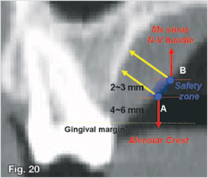
Figure. 20 Determination of the implant site and insertion angle: It is very dangerous for the implant to be placed close to the root apex. The apical end of an implant should not extend beyond the root apex because this will cause increased risk of injury to both the maxillary sinus and the neurovascular bundle. The gingiva in this area is also very thick and is not suitable for implant placement.
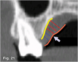
Figure. 21 Vertical positioning: The implant should be placed in the apical area 1/3 to 1/2 of the distance between the alveolar bone crest and root apex. Thickness of soft tissue has an influence on the determination of the vertical position of an implant. It is not efficient to insert an implant superior to the breakpoint where the gingiva begins to thicken. The gingiva thickens rapidly around the parts in which the submucosal layer starts. It is preferable that the implant is not placed apically to the area where the soft tissue begins to thicken and it is safer if the end of the implant does not exceed the root apex.
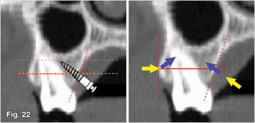
Figure. 22 Implantation angle: The principle is the same as that with buccal implants; an oblique insertion is recommended to decrease the risk of root injury and to attain more available space (a). and the implant should be placed at an angle of 30-45 degrees to the occlusal plane. On the contrary, palatal alveolar implants should be inserted perpendicular to the cortical bone from the beginning to the end without changing the insertion angle because the palatal slope of cortical bone is different from that of buccal bone.
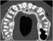
Figure. 23 Implantation angle: Furthermore, the implant should be placed perpendicularly mesio-distally. A direct approach (red arrow) to the maxillary palatal alveolus is not recommended because there is a possibility that the risk of root injury will increase since the implanting angle is horizontally slanted. Hence, the indirect approach (blue arrow) using contra-angled instruments is recommended for insertion at a right angle.
Midpalatal area
Precautions should be considered to prevent injury to the nasopalantine canal or nasal cavity (figure 24, 25, 26, 27, 28).
The thick cortical bone provides excellent primary stability and the risk of irreversible injuries to anatomical structures is relatively low. In this area, there are no structures that will interfere with orthodontic tooth movement. Additionally, the palatal side provides enough space to allow for the use of lever arms to control the line of action. The condition of soft tissue is also suitable for implantation because the soft tissue in this area is the mucoperiosteum . However, accessibility is poor, and in order to be used for treatment, construction of additional transpalatal attachments may be required. Consequently, the use of transpalatal appliances tends to increase patient discomfort (figure 29). Furthermore, the risk of surgical trauma during implantation is high because of the thick cortical bone and since blood supply is poor, the healing potential is low. Additionally, hard bone renders a high risk of implant fracture during the insertion procedure. Low accessibility makes matters worse.
When using the indirect approach with contra-angled instruments, a long neck driver and a long neck drill should be used to prevent premature blockage by the anterior teeth(figure 31, 32).
The patient will feel "pressure" under the nose during or after insertion.
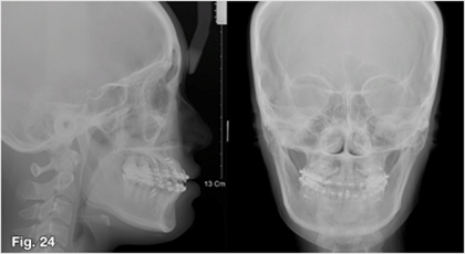
Fig. 24 Little information can be obtained from lateral cephalometric radiography because the available bone quantity of the midpalate is often underestimated. In lateral cephalometry, instead of the bone quantity of the mid-sagittal plane, the bone quantity of the para-sagittal plane begins to appear.
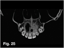
Fig. 25 The nasopalatine canal passes in the front portion of the maxilla, and the nasopalatine foramen opens behind the lingual side of the central incisors. The neurovascular bundle also passes through the nasopalatine canal, so caution is needed to prevent injury.
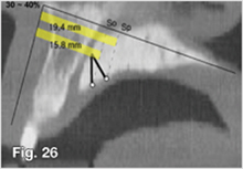
Fig. 26 A safety zone was measured using three-dimensional CT when a 6mm long implant was placed in the mid-palatal suture area. On average, in the case of implantation perpendicular to the occlusal plane and to the palatal bone surface, there is little possibility of damage to the nasopalatine canal only when an implant is inserted into the points 15.8mm and 19.4mm posterior to the ANS on the ANS-PNS line, respectively. It may not be safe to insert an implant in the anterior 30%-40% portion on the ANS-PNS line from the mid-sagittal plane.
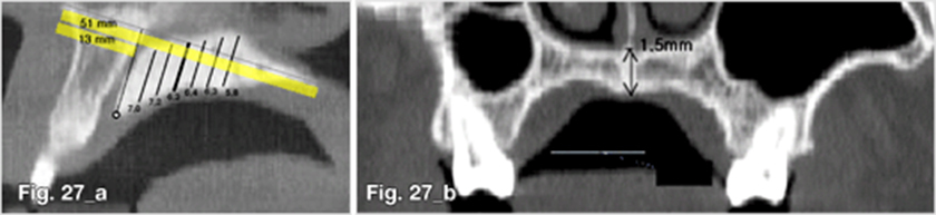
Fig. 27 A figure 27a shows the vertical bone quantity available for inserting an cylindrical implant of 1.5mm in diameter in the mid-sagittal plane (b). Normally, there is enough bone for implantation.
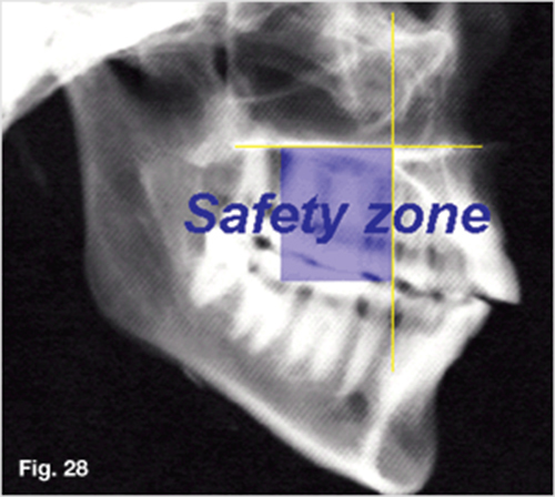
Fig. 28 Antero-posterior positioning of insertion in the maxillary midpalatal suture area: the anterior 40% of the mid-sagittal plane is a dangerous area. The middle 40% on the ANS-PNS line is a safe area. The lateral Ceph shows which part is appropriate for implantation on the basis of tooth position.
Fig. 29 An attachment is needed to use midpalatal implants.
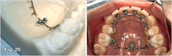
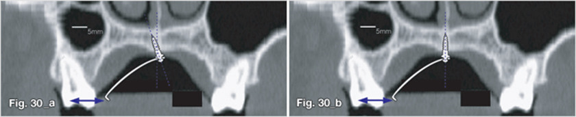
Fig. 30 Insertion angle: according to the design of the attachment and the amount of orthodontic force needed, it may be better to implant obliquely slightly to the left and the right sides (a) than to implant vertically (b).
Selection of implant
Generally, a regular type implant is sufficient.
Determination of insertion site
Anterior-posterior position: To avoid injury to the nasopalatine canal, a lateral cephalogram should be used as a guide and an implant should not be placed in the area 40% anterior to the mid-sagittal plane. Placement in the middle 40% is recommended when considering safety .
Transverse position: The midpalatal area is the place where cortical bone meets (figure 27); thus, bone quality is excellent. In terms of the quantity of bone, implantation on the midplatal suture is desirable.
From the view of bone quality, the results may or may not be desirable. In cases in which the bone quality of the buccal area is inadequate, midpalatal suture areas where cortical bone meets are good for obtaining primary stability. However, the bone quality in the midpalatal suture area may be extremely hard, especially in male patients with low mandibular angles. The stability in these cases would be rather low because of surgical trauma induced by frictional heat and physical pressure from the hard cortical bone. The risk of implant fracture also increases. Therefore, insertion of an implant slightly separated from the mid-sagittal plane or into the para-sagittal plane is preferred where hard bone is expected.
Insertion of an implant slightly away from the mid-sagittal plane is also preferred in cases in which sutural growth is still occurring in growing patients.
Implantation angle: The implant should generally be inserted perpendicular to the bone surface in order to secure the quantity of available bone. When direct insertion is performed, the implant has a tendency to tilt forward due to limitations in opening the mouth, yet slight anterior tilting does not seem to present any clinical problems.
In cases in which one implant is used with an attachment, an implant may be inserted with an antero-posterior angulation or with a lateral angulation for higher resistance to orthodontic forces (figure 30).
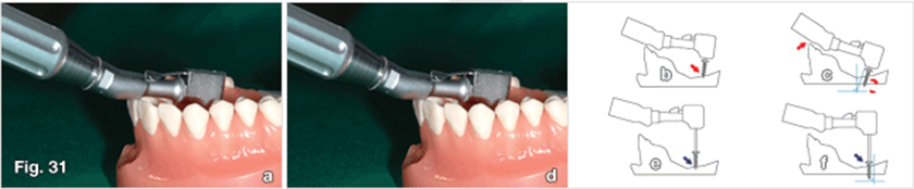
Fig. 31 In the case in which a short driver tip is used, it is likely that wobbling occurs because the implant is caught in the upper central incisor tip (a,b,c). In other words, the path of insertion changes when the implant is; this damages cortical bone, which provides primary stability. Therefore, the neck of the driver tip should be of an appropriate length (d, e, f).
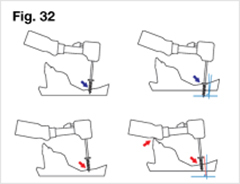
Fig. 32 Even in using a long driver tip, wobbling or caught in the upper central incisor may occur according to insertion angle.
Anterior nasal spine and anterior alveolus areas
In the anterior alveolus, there is comparatively limited available space because of narrow interdental and labio-lingual dimensions (figure 33, 34). Patient discomfort from the implant and stress from the surroundings may be relatively high because of perioral muscle activity. The steep slope of the labial side of the anterior alveolar bone may lead to impingement of soft tissue.
However, the bone quality in this area is favorable and is able to provide good primary stability while also being an ideal position for delivering intrusive forces to the anterior teeth with a labioversion vector.
This is useful in the case of Class II div. 2. Depending on the condition of the frenum, the open method or the closed method should be chosen (figure 35, 36). In the closed method, the implant head is not exposed and only the wire extension is exposed.
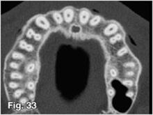
Fig. 33 The available interdental space of the anterior teeth is lower than that of the posterior teeth. Moreover, the available buccolingual space of the anterior teeth is lower than that of the posterior teeth.
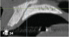
Fig. 34 Because the nasopalatine canal is located at the lingual side of the central incisor, there is almost no risk of injury to the neurovascular bundle of the nasopalatine canal when placing implants in the anterior alveolus. The major problem in using the anterior alveolus is that the labial slope of the anterior alveolus makes oblique insertion impossible. The available space diminishes because of this, which then requires apical insertion, and this may increase the potential of the implant being readily covered by the mucosa.
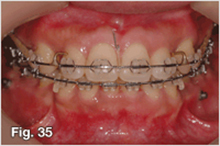
Fig. 35 Even in the anterior alveolar area, there are few problems with soft tissue if the frenum location is high. In these cases, the patient feels relatively little discomfort.
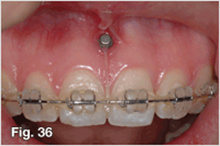
Fig. 36 In cases in which the frenum is lower, there is a possibility that the implant will be buried if a frenectomy is not accompanied. When intruding and retracting the anterior teeth using anterior interdental implants, the elastic chains and implant have a likelihood of being buried into the soft tissue as teeth move. Therefore, a closed method using an extension wire might be advisable in those cases.
Rugae area
The quality and quantity of bone in this area are good for implants. Although the soft tissue is thick, it is keratinized and of good condition. Nevertheless, the tongue is located in this position, so discomfort to the patient or stability during the initial healing period may be affected. Implants in rugae area can be utilized for mesial movement of molars in adult patients, for orthopedic application, and for molar distalization in growing patients. Like any palatal implants, it is advantageous to control the line of action by changing the point of force application.
Following anesthesia, the thickness of the soft tissue should be measured using a periodontal probe prior to implantation using a periodontal probe. The implant should be chosen according to the thickness of the soft tissue.
In the rugae area, the midsagittal plane should be avoided as not to injure the nasopalatine neurovascular bundle.
Infrazygomatic crest area
While there was a low success rate observed in the maxillary buccal alveolus area in the early days of mini-implants, much attention was drawn to the infrazygomatic crest area because of its superior cortical bone quality, which provides higher primary stability. Moreover, the fact that the location of the implant is much higher serves to be advantages. This is favorable for the application of intrusion forces and does not cause any interference to the movement of adjacent teeth. However, because it is in the vestibular area, there is considerable movement of soft tissue and the implant may be covered readily. Not only does this make the open method difficult to apply, but there is also a relatively high risk of the development of soft tissue problems (figure 37). Since the implant is inserted in a higher position, bone quantity may be insufficient, thus increasing the risk of maxillary sinus injury.
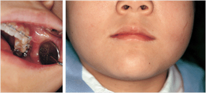
Fig. 37 In the infrazygomatic crest area, soft tissue moves a great deal. This movement increases the risk that the implant will be buried by the mucosa and is likely to cause soft tissue problems. An implant in the infrazygomatic crest area caused an abscess (a), which caused the cheek to swell (b). The implant was removed and general antibiotics were prescribed.
Maxillary tuberosity
Though this is a favorable position for the delivery of distalizing forces, accessibility is poor, and thus, implantation may become inaccurate. Furthermore, bone quality may not be sufficient due to pneumonization of the maxillary sinus, especially in edetulous areas. Pre-surgical examination using panoramic radiography is necessary.
- 상호 : (주)오솔루션
- 대표자 : 김정문
- 주소 : 서울 강동구 양재대로 1371 (성내동) 207호
- TEL : 02-483-1212
- FAX : 02-478-0735
- 사업자 등록번호 : 212-81-63456
- EMAIL : orlus@ortholution.com
- Copyright(c) (주)오솔루션. All Rights Reserved.

